
Frequently asked questions / Troubleshooting
Dongle / License issues (6)
To update your licenses, we will need your dongle information in form of a .c2v file since the update will be created for your particular dongle.
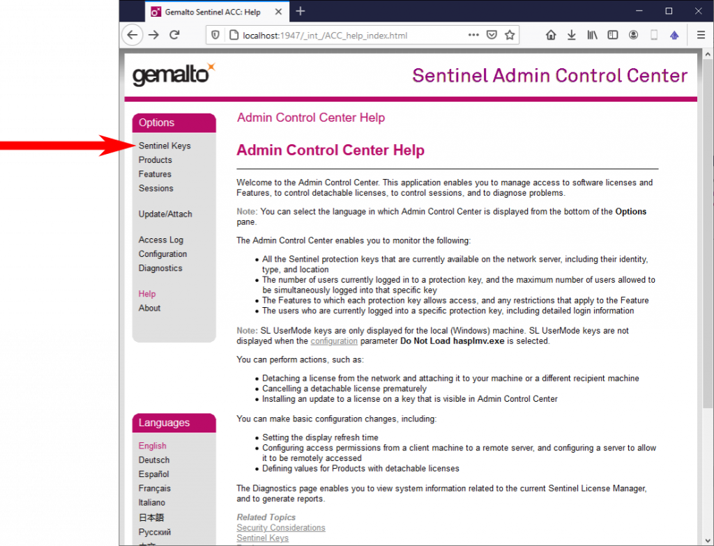
To create this .c2v file, please open your browser at the PC where the dongle is used and visit http://localhost:1947 or select Help => Check licenses via thaTEC:Core’s menu bar. On the main page, please select Sentinel keys from the menu on the left:
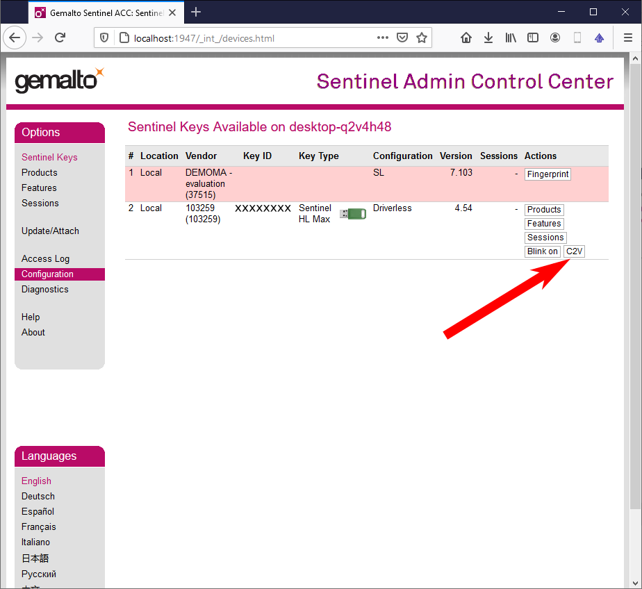
On the following page, a list of all connected dongles will appear. In case of multiple present dongles, select the dongle you want to update and click on the button C2V in the according entry:
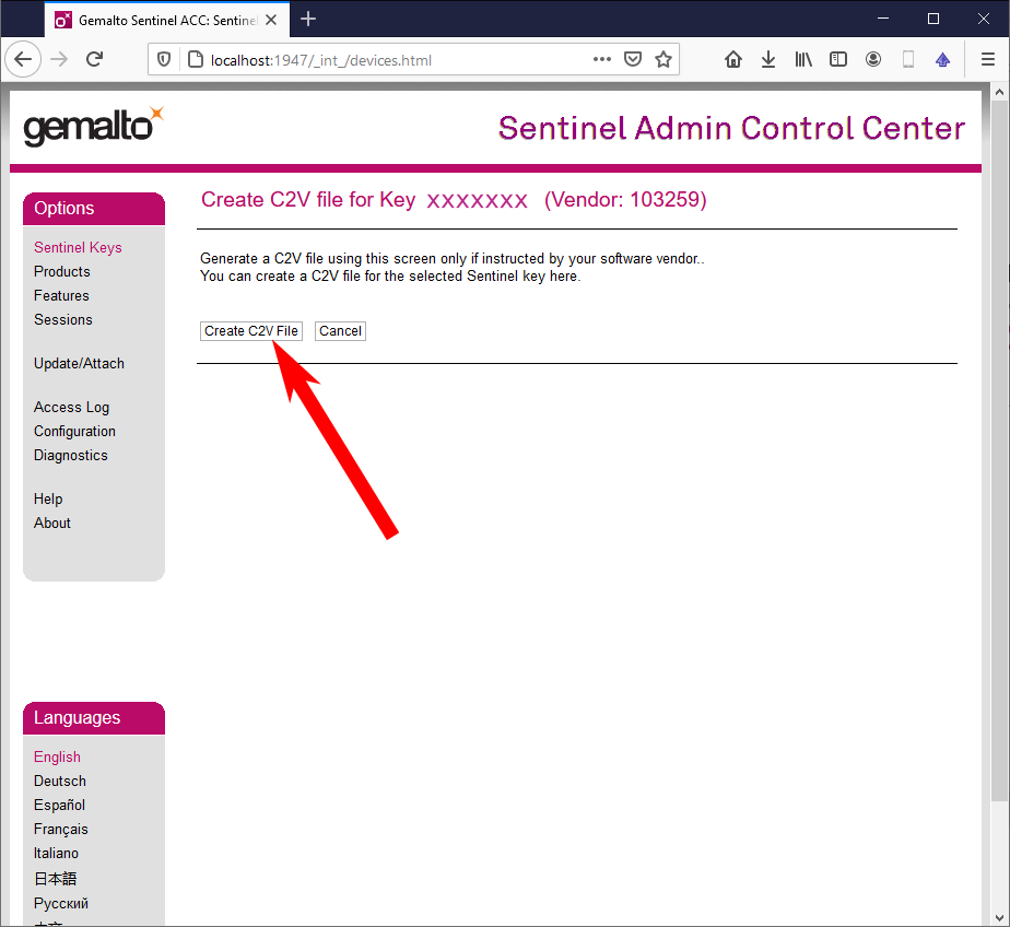
On the C2V page, select Create C2V File. This will start the download of the required c2v file:
To update your license, we will send you a .V2C file with the updated license information (see also How to activate/update your licence).
Attach the dongle to one of the PCs in your network, start this PC, and make sure that port 1947 is released on all machines. Please also refer to section 1.2 of the thaTEC:OS user manual or contact us under contact@thatec-innovation.com if the error persists.
Visit http://localhost:1947 to check whether Sentinel LDK is installed. If not, please run the thaTEC:Core installer again which can be found in our download section. If the error persists, please refer to section 2.2 of the thaTEC:OS user manual or contact us under contact@thatec-innovation.com.
This error message appears if you try to open software modules like, e.g., thaTEC:OS or thaTEC:TFPDAS5, which are based on single-user licenses, and all licenses are alrady in use. There are several reasons for this to happen:
- Another instance of this software is already running(e.g. someone is using thaTEC:OS for data evaluation instead of the DataInspector, see also the remark below)
- The license is used by another PC within your network
- The module was not closed cleanly or your PC crashed and the license was not released
Remark: Even though thaTEC:OS offers the option to visualize your data, it should only be used for quick checks or during measurements. Please keep in mind that a running instance of thaTEC:OS might block one of your licenses. For the evaluation of data the use of the license free thaTEC:DataInspector is strongly recommended!
Important Note: Be careful performing the following steps and only do this if the according software did not exit cleanly! Disconnecting sessions that are currently in use will exit the according software using this license!
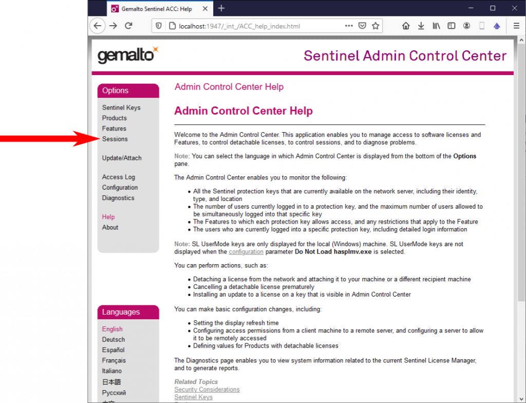
To check all current sessions, perform the following steps on the PC to which the dongle is connected to. To check all current sessions, select Help => Check licenses via thaTEC:Core’s menu bar or manually visit http://localhost:1947 and select Session from the menu on the left:
On the following page, you can see all current sessions to the connected dongle, including the information on the PC and user currently using the feature. In order to release the license, press on the Disconnect button of the according session:
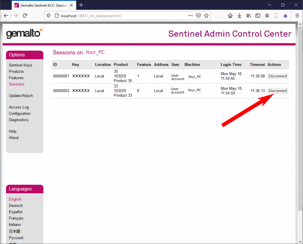
For more information, please have a look at Section 2.1 of the thaTEC:OS user manual.
Most modules from our device library can be freely used with a standard thaTEC:OS license. However, to use some modules like, e.g., thaTEC:TFPDAS5, you will need to purchase an according license. Thus, if the above error message occurs, your dongle might not have the corresponding feature/license.
If you are interested in purchasing the according license, please contact us under contact@thatec-innovation.com.
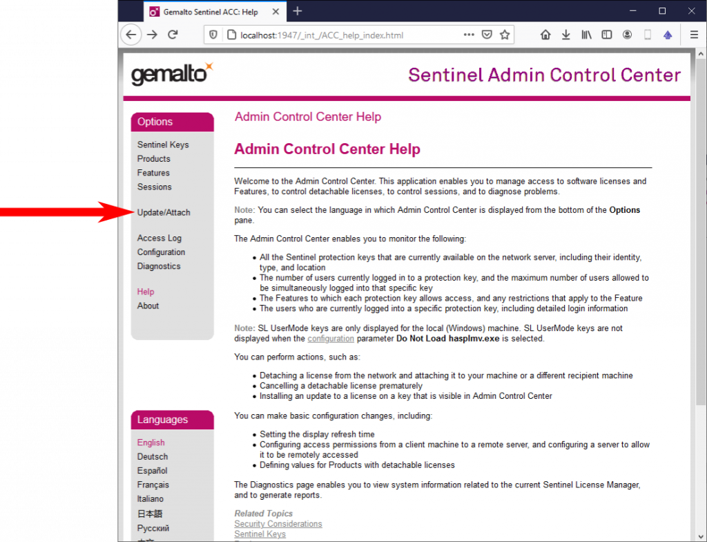
If you purchase any of our software modules, you will receive a Sentinel Max HL USB dongle via mail. However, we always ship these dongles without any license information which will be provided via mail in form of a .V2C file. To activate or update your license, after the installation of thaTEC:Core, insert the dongle to the according PC, open thaTEC:Core and select Help => Check licenses via thaTEC:Core’s menu bar or visit http://localhost:1947 using your browser. On the browser page, select Update/Attach from the menu on the left:
Select the according .V2C file that you have received and press the Apply File button:
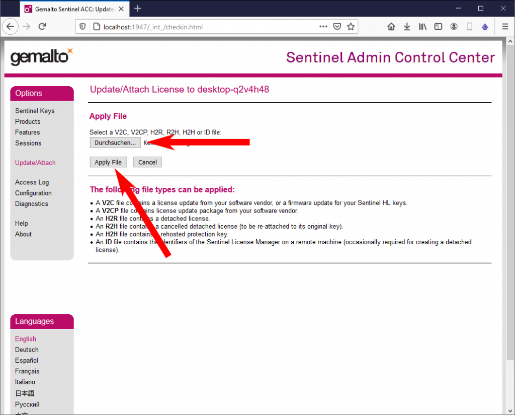
Now you should receive a message that informs you about the successful update of your license.
Important note: If you purchased more than one dongle from us, it is important that the dongle and the .V2C file matches! Any .V2C file will only work one specific dongle!
General topics (13)
Devices connected to the PC via USB or GPIB are usually automatically detected and can be selected from the dropdown list of the Device address control. Devices which are connected via ethernet are not detected automatically but the device adderss must either be entered manually in the form
TCPIP[board]::host address[::LAN device name][::INSTR]
e.g. TCPIP0::192.168.0.1::INSTR
or the device can be added to the device list using NI MAX. For instructions and more information, visit
https://www.ni.com/getting-started/set-up-hardware/instrument-control/ethernet-connect
If you are using a PC without an internet connection in your lab, you can still conventiently add and update all our software modules using a second PC with an active internet connection. To do so, just follow the description below.
Prerequisite:
thaTEC:Core must be installed on both PCs. For this, download our (offline) installer from the Download section of our homepage.
Step 1: Download/Update module database
Using the PC with an active internet connection, select Modules => Download modules to local folder from thaTEC:Core’s menu bar and select the target folder (e.g. a USB stick).
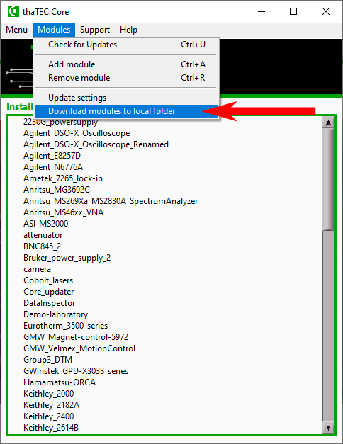
Reduce download time: Before starting the download, thaTEC:Core will check all files that are already present in the selected folder and compare them to the files on our server. Thus, by always selecting the same folder for the downloads, the download time can drastically be reduced since only updated files are being loaded!
Step 2: Update settings
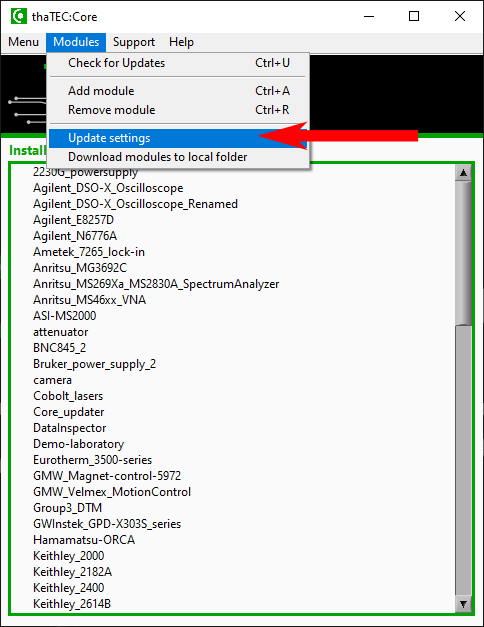
After the download has finished, transfer the downloaded files to the PC without internet connection (i.e. connect the USB stick to the PC). To use the offline database, you need to adjust the according settings. For this, select Modules => Update settings from the menu bar:
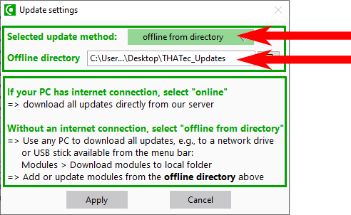
Subsequently, selet Offline from directory as update method and select the according folder where the downloaded database are located (i.e. the USB stick) and apply the settings:
From here, you can update and add new devices from our database identical to the case with an active internet connection.
Device module cannot connect to thaTEC:OS
=> Solution: Check connection settings in thaTEC:OS and in the device module via the menu bar > Communiation > Settings. If thaTEC:OS and the device module are on the same PC use the same PC setting.
If you are using an AMD (inparticular AMD Ryzen) processor, you might encounter this issue during the startup of some of our software modules like, e.g., thaTEC:OS or the DataInspector.
With recent versions of thaTEC:Core, this issue is solved automatically after eventually (once) granting Admin rights after the startup of thaTEC:Core.
In order to solve this issue manually, you need to add a new environmental variable named “MKL_DEBUG_CPU_TYPE” with a value of “5”.
To do so, please follow this procedure:
- Press the windows key, type “environment“, and select “edit the system environment variables“.
- In the System Properties window, click on the “Environment Variables” button.
- In the upper “User Environment Variables” section, select “New“.
- Insert “MKL_DEBUG_CPU_TYPE” in the field “Variable Name“.
- Set “5” as “Variable Value“.
- Apply the changes and reboot your PC.
If you still encounter this issue, please contact us under contact@thatec-innovation.com
This can happen due to driver issues after updating NI drivers
=> Solution: 1) Remove NI488 drivers, 2) reinstall thaTEC:Core, 3) DO NOT update NI products!
It is possible to open the current changelog of the module before installing the update. For this, just right click on the respective module and select “Update” => “Open updated changelog”
In the latest versions, we changed the self-update procedure of thaTEC:Core. Thus, if you are using an older version (before 2019-08-06), the update is not always performed correctly and it might still be indicated that a new update is available. In this case, please download the Core_updater module from the module library and run this module to manually perform the update.
This can happen if the Windows display settings has been set to a scaling value of larger than 100%. We try to develop our software modules in a way that this does not happen. However, if you are having trouble with this, the best solution is to set the display scaling to 100%.
If you encounter an issue with any software module, e.g., some features not working correctly, it is of great help for us if you attach the logfile of the according software module. This will help us to identify and solve the issue.
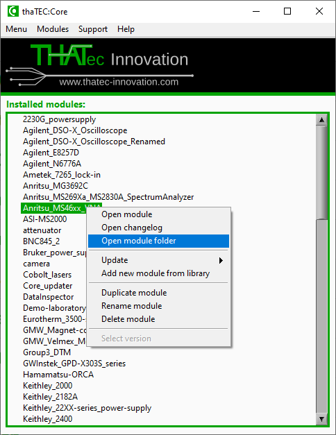
The logfile (logfile.db) is located in the corresponding module folder. To open the folder, right click on the module in thaTEC:Core and select Open module folder:
Accessing the data file with, e.g., the thaTEC:DataInspector during the measurement can cause issues due to the simultaneous file access.
=> Solution: Check your live data only via thaTEC:OS !
See also Problems with reading/writing files
Developing software modules for your hardware usually requires a debugging process. If the according PC is connected to the internet, the easiest way to debug the software is to schedule a remote support session with us so we can directly access your PC and debug the software modules.
Please note that no additional software needs to be installed!
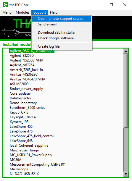
To open a remote support session select Support => Open remote support session from thaTEC:Core’s menu bar:
The module might take some time to start. However, if any error message occurs or nothing happens, please update the support database as described here.
After the startup of the remote support module, the following window will appear, waiting for our remote access:
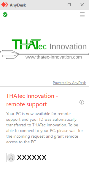
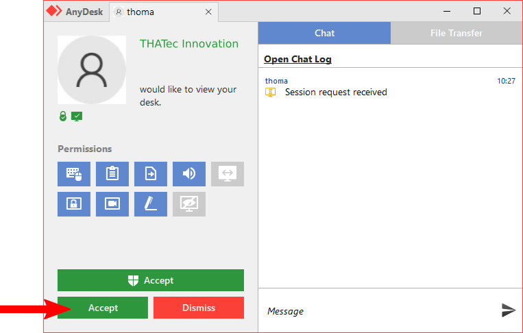
After connecting to your PC, you will need to grant access to your PC via the following window which will appear and will remain during the whole session allowing, e.g., to write text messages and stay in touch during the remote session:
Important note: During the remote support session, we will only have control over your mouse and keyboard as long as you are not using it. Thus, please do not use the accoring PC for other tasks during a remote support session!
1) Is your file path to long? (Path length is restricted to 260 characters by Windows)
=> Solution: Try to copy file to another location / change file path
2) Check file or folder names for special characters
3) Accessing the data file with, e.g., the thaTEC:DataInspector during the measurement can cause issues due to the simultaneous file access.
=> Solution: Check your live data only via thaTEC:OS !
During the connection process of a driver module to thaTEC:OS, the min/max values for each control are obtained from the properties of the individual controls and transmitted to thaTEC:OS. If the min/max values in the scan definition are not correct, there are possible origins.
1) The min/max values of the control were changed during the program runtime after the connection to thaTEC:OS. In this case, the properties need to be re-sent using the properties.vi. Please see also the example in the programming template (current range control).
2) Check the representation of your control. For example, currently, single precision (SGL) values are not recognized, thus, please change the representation of the control to integer or double precision.
thaTEC:Core (7)
If you are using a PC without an internet connection in your lab, you can still conventiently add and update all our software modules using a second PC with an active internet connection. To do so, just follow the description below.
Prerequisite:
thaTEC:Core must be installed on both PCs. For this, download our (offline) installer from the Download section of our homepage.
Step 1: Download/Update module database
Using the PC with an active internet connection, select Modules => Download modules to local folder from thaTEC:Core’s menu bar and select the target folder (e.g. a USB stick).

Reduce download time: Before starting the download, thaTEC:Core will check all files that are already present in the selected folder and compare them to the files on our server. Thus, by always selecting the same folder for the downloads, the download time can drastically be reduced since only updated files are being loaded!
Step 2: Update settings
After the download has finished, transfer the downloaded files to the PC without internet connection (i.e. connect the USB stick to the PC). To use the offline database, you need to adjust the according settings. For this, select Modules => Update settings from the menu bar:

Subsequently, selet Offline from directory as update method and select the according folder where the downloaded database are located (i.e. the USB stick) and apply the settings:

From here, you can update and add new devices from our database identical to the case with an active internet connection.
It is possible to open the current changelog of the module before installing the update. For this, just right click on the respective module and select “Update” => “Open updated changelog”
In the latest versions, we changed the self-update procedure of thaTEC:Core. Thus, if you are using an older version (before 2019-08-06), the update is not always performed correctly and it might still be indicated that a new update is available. In this case, please download the Core_updater module from the module library and run this module to manually perform the update.
Developing software modules for your hardware usually requires a debugging process. If the according PC is connected to the internet, the easiest way to debug the software is to schedule a remote support session with us so we can directly access your PC and debug the software modules.
Please note that no additional software needs to be installed!
To open a remote support session select Support => Open remote support session from thaTEC:Core’s menu bar:

The module might take some time to start. However, if any error message occurs or nothing happens, please update the support database as described here.
After the startup of the remote support module, the following window will appear, waiting for our remote access:

After connecting to your PC, you will need to grant access to your PC via the following window which will appear and will remain during the whole session allowing, e.g., to write text messages and stay in touch during the remote session:

Important note: During the remote support session, we will only have control over your mouse and keyboard as long as you are not using it. Thus, please do not use the accoring PC for other tasks during a remote support session!
When renaming or duplicating modules in thaTEC:Core, in some cases a warning or an error message will occur since renaming/duplicating this module might lead to malfunction in an automated measurement using thaTEC:OS.
Potential errors caused by renameing/duplicating:
When using the modules with thaTEC:OS, the names as displayed in the device tree at the left side of the user interface must be unique. Usually, this name corresponds to the folder name in the module folder since this ensures unique names as displayed below:
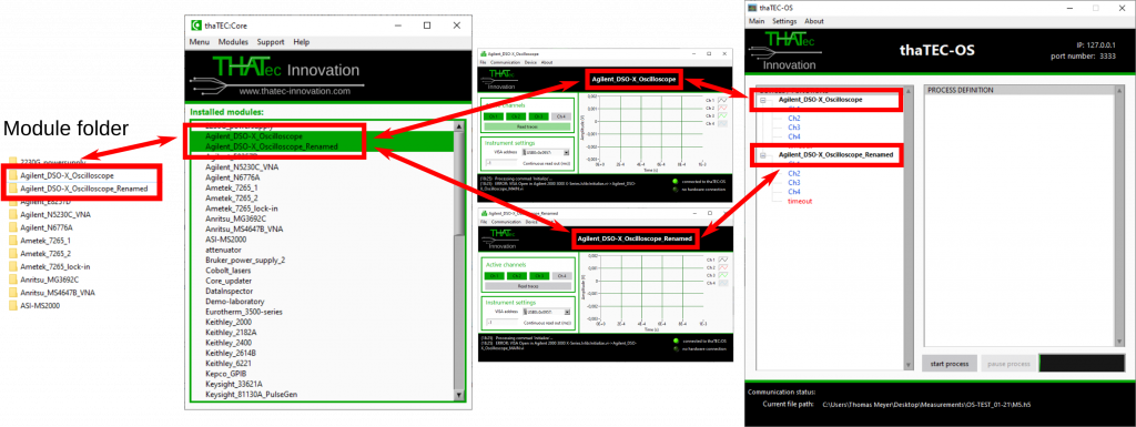
However, in older versions of some device modules or in the case of a self-programmed module, the module name might be hard-coded, leading to identical names of different modules when connected to thaTEC:OS and, hence, to malfunction.
Thus, when a warning message in thaTEC:Core appears, in particular when duplicating a module, it must be ensured that the module name on connecting to thaTEC:OS is also adjusted! In these cases, it is strongly recommended to open the module, connect it to thaTEC:OS and check if the name has been adjusted. If not, you might need to update to a later version of the device module or change your own sourcecode accordingly.
Before releasing new features for a certain module, usually, there will be a beta version to find potential bugs before releasing a stable version.
To update to a new beta version, e.g. for debugging the software, open thaTEC:Core and make sure that the update database of thaTEC:Core is up-to-date by checking for updates via the menu bar “Modules” => “Check for updates” or by pressing Ctrl+U.
Afterwards, right-click on the module you want to update and select “Update” => “Update to newer beta version”
Via thaTEC:Core, it is possible to directly access the manuals for several software modules, open remote support sessions or perform other quick checks for your system if any errors occur.
With recent thaTEC:Core versions, all support functionalities are automatically kept up to date if the PC has an active internet connection. Also, when performing offline updates, the support database will be automatically updated.
In order to perform a manual update or to update the support database in older versions of thaTEC:Core, please perform the following steps:
- Check for updates via the menu bar => Modules => Check for updates
- Select Help => Update documentation from the menu bar
If this option is greyed out, there are no updates for the support database available. When performing offline updates, please ensure that your offline database is up to date!
thaTEC:OS (6)
Device module cannot connect to thaTEC:OS
=> Solution: Check connection settings in thaTEC:OS and in the device module via the menu bar > Communiation > Settings. If thaTEC:OS and the device module are on the same PC use the same PC setting.
If you are using an AMD (inparticular AMD Ryzen) processor, you might encounter this issue during the startup of some of our software modules like, e.g., thaTEC:OS or the DataInspector.
With recent versions of thaTEC:Core, this issue is solved automatically after eventually (once) granting Admin rights after the startup of thaTEC:Core.
In order to solve this issue manually, you need to add a new environmental variable named “MKL_DEBUG_CPU_TYPE” with a value of “5”.
To do so, please follow this procedure:
- Press the windows key, type “environment“, and select “edit the system environment variables“.
- In the System Properties window, click on the “Environment Variables” button.
- In the upper “User Environment Variables” section, select “New“.
- Insert “MKL_DEBUG_CPU_TYPE” in the field “Variable Name“.
- Set “5” as “Variable Value“.
- Apply the changes and reboot your PC.
If you still encounter this issue, please contact us under contact@thatec-innovation.com
Accessing the data file with, e.g., the thaTEC:DataInspector during the measurement can cause issues due to the simultaneous file access.
=> Solution: Check your live data only via thaTEC:OS !
See also Problems with reading/writing files
1) Is your file path to long? (Path length is restricted to 260 characters by Windows)
=> Solution: Try to copy file to another location / change file path
2) Check file or folder names for special characters
3) Accessing the data file with, e.g., the thaTEC:DataInspector during the measurement can cause issues due to the simultaneous file access.
=> Solution: Check your live data only via thaTEC:OS !
When renaming or duplicating modules in thaTEC:Core, in some cases a warning or an error message will occur since renaming/duplicating this module might lead to malfunction in an automated measurement using thaTEC:OS.
Potential errors caused by renameing/duplicating:
When using the modules with thaTEC:OS, the names as displayed in the device tree at the left side of the user interface must be unique. Usually, this name corresponds to the folder name in the module folder since this ensures unique names as displayed below:

However, in older versions of some device modules or in the case of a self-programmed module, the module name might be hard-coded, leading to identical names of different modules when connected to thaTEC:OS and, hence, to malfunction.
Thus, when a warning message in thaTEC:Core appears, in particular when duplicating a module, it must be ensured that the module name on connecting to thaTEC:OS is also adjusted! In these cases, it is strongly recommended to open the module, connect it to thaTEC:OS and check if the name has been adjusted. If not, you might need to update to a later version of the device module or change your own sourcecode accordingly.
During the connection process of a driver module to thaTEC:OS, the min/max values for each control are obtained from the properties of the individual controls and transmitted to thaTEC:OS. If the min/max values in the scan definition are not correct, there are possible origins.
1) The min/max values of the control were changed during the program runtime after the connection to thaTEC:OS. In this case, the properties need to be re-sent using the properties.vi. Please see also the example in the programming template (current range control).
2) Check the representation of your control. For example, currently, single precision (SGL) values are not recognized, thus, please change the representation of the control to integer or double precision.
thaTEC:TFPDAS5 (5)
To manually control the Piezos, position the cursor over the according piezo position indicator in the lower left of the main window, press Ctrl and use the mouse wheel to control the piezo.
If this does not work, check the alignment settings via menu bar => Paremeter => Alignment. Select the Handbox tab and check that the Handbox Tilt Fine [V] value is non-zero.
Hint: Switch off the stabilization routine during manual control by clicking on the three round buttons next to the numeric indicators on the left of the main window. A green button indicates the according stabilization being active, a red button shows that the stabilization is switched off.
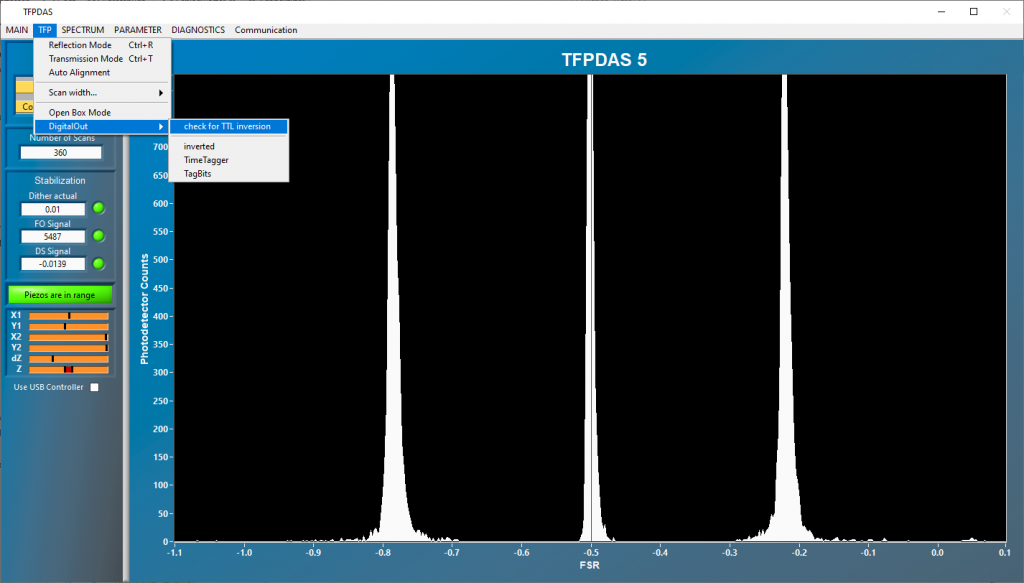
Due to different hardware versions, the TTL outputs which set the alignemnt/tandem mode of the TFPI during normal operation have to be inverted. To check this, TFPDAS5 offers a feature to check for the inversion.
Important: Before starting the check, TFPDAS must be in idle mode! For this, press Escape which stops any acquisition. Subsequently, select from the menu bar => TFP => DigitalOut => check for TTL inversion:
Cause: Handbox Tilt Fine value is too small
=> Solution: Open the Alignment parameters window via the menu bar >PARAMETER > Alignment or by pressing Ctrl + F5 and switch to the Handbox tab. Increase the Handbox Tilt Fine value (second from bottom). Good values are 0.02 – 0.04.
The interferometer is scanning but the number of scans does not increase and no signal is obtained
A possible cause for this is a very large signal which exceeds the spike limit value. The spike limit should suppress spikes in the spectrum which can occur from time to time and which are usually limited to one channel. Thus, if the intensity of a channel exceeds the spike limit value, the current scan is discarded. However, if the signal is very strong and exceeds the spike limit value, all scans exceed the limit and will be discarded resulting in the mentioned behavior. To solve this, increase the spike limit value in the scan parameter window.
Check the Dynamic dither settings via the menu bar > PARAMETER > Stabilize or by pressing Ctrl + F8. The FO dither threshold should be at ~70% of the maximum FO signal which is constantly shown on the left side of the main window. Also a too high FO Dither max value or a too small FO Dither min value might cause issues. A good maximum value is 0.01 – 0.02, good minimum values are 0.004 – 0.002.
Time-resolved BLS / Time Tagger (3)
Correct trigger levels are crucial for a correct operation of the Time Tagger software module.
To adjust the trigger levels, open the device settings window via the menu bar => Device => Hardware settings
Make sure that the channel number settings matches the input connections at the hardware. Subsequently, adjust the trigger levels of each channel. To check the settings, activate the Check trigger levels button at the bottom of the window. Not in the counts/s row, the current countrates of each channel are displayed. Check if the countrates match the input signals:
- Start signal: Repetition of the pulse generator
- Stop signal: Bring the TFPI into reflection/alignment mode and check the signal intensity. Note: the expected countrate depends on the scanning speed (ms/channel) of thaTEC:TFPDAS! Example: overall intensity: 400 counts/channel and scan speed 1 ms/channel => expected average countrate: 400.000 counts/s
- Counter: With thaTEC:TFPDAS in measurement mode (spectrum is being acquired), the countrate of this channel should match half the scanning speed (ms/channel). Please note that during the retract of the interferometer mirrors, no signal is applied to this channel reducing the expected average countrate. Example: scan speed 1 ms/channel => expected average countrate: 500 counts/s.
- Reset: The trigger level should be the same as for the counter channel. The expected countrate should match the rate of acquired scans of thaTEC:TFPDAS during a measurement.
- Gate: The trigger level should be the same as for the counter and the reset channel and also match the rate of acquired scans of thaTEC:TFPDAS during a measurement times the number of (non overlapping) ROIs. Example: thaTEC:TFPDAS is scanning with a speed of 1 scan per second and there are 2 ROIs => Expected countrate: 2 counts/s.
Important Note:
Even if the count rates (in particular for the stop channel/detector) match the expectations, a too low value might result in a wrong timing since some pulses might be detected earlier than others due to variations of the pulse shape. Thus, always check if the acquired signal matches the expectations. Below, the result for a 50 ns long pulsed excitation is shown with incorrect (left) and correct (right) trigger level settings displaying the effect on the acquired data.
Background:
Time-resolved Brillouin light scattering measurements always include two separate deviced, i.e., the Tandem Fabry-Pérot interferometer and the Time Tagger and their according software modules which have to be synchronized.
This synchronization is achieved by a hardware- and software synchronization and the latter must be taken into account when setting up an automated time-resolved measurement.
The reasons/background are:
- The Time Tagger software can, in principle, start the TFPDAS software
- But, the Time Tagger software is NOT notified if an error occurs in the TFPDAS software
- The Time Tagger software is not notified when a spectrum is acquired
- The Time Tagger software cannot read out the TFPDAS spectrum
Thus, a certain measurement procedure is required as described below.
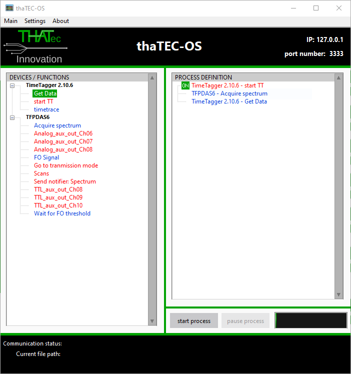
Measurement procedure (see also image below):
- Arm the Time Tagger via the “start TT” command: This activates the Time Tagger software. However, due to the hardware synchronization, signal will only be acquired when the TFPI is actually scanning. Thus, there can be an arbitrary delay between the arming of the Time Tagger and the acquisition of the spectrum.
- “Acquire spectrum” command to the TFPDAS software: This will start the acquisition (and, hence, the acquisition of the time-resolved signal since the Time Tagger has been armed before). Furthermore, this command will wait for the acquisition to finish!
- “Get data” command to the Time Tagger software: This will return the 2D time- and frequency-resolved measurement data.
Depending on the date of purchase of your license, your dongle has feature 19 or feature 21 activated for time-resolved Brillouin light scattering measurements using a Time Tagger from Swabian Instruments.
Thus, after downloading the software if a license error occurs on the first startup even though the USB donlge is present, you need to manually select the feature. To do so, select File => License setting from the menu bar and select Feature 19 or Feature 21 according to your license and restart the application.
